Survey Settings
The Survey Settings define the standards and behavior used when creating a field book and objects generated by survey data. The Default Survey Settings are stored in a DGNLIB file and then copied to the active DGN when used.
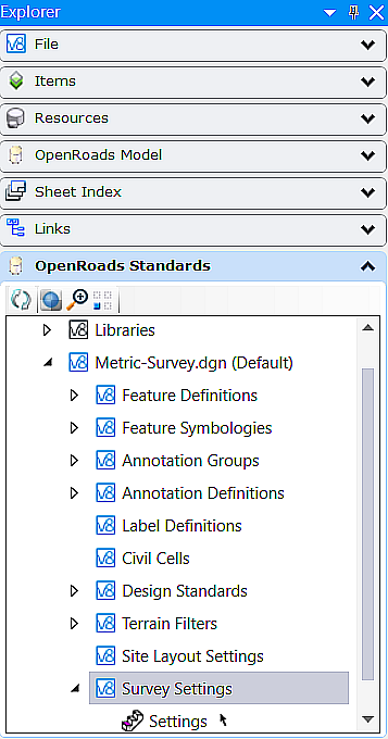
To access Survey Settings, go to Ribbon: Explorer > OpenRoads Standard > Standards > Survey Settings
Survey Properties
The properties dialog displays all the properties of the survey feature. The survey features are described below.

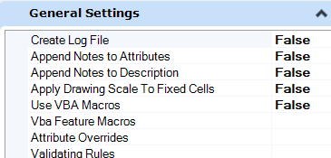
General Settings
General settings contain settings for Creating Log File, Append Notes to Descriptions, Use Annotation Scale, Using VBA Macros, VBA Feature Macros, and Validating Rules.
Create Log File is a True/False setting that turns on/off whether, or not a log file is created of the users' surveying import and editing activities. The Log File is created in the same folder as the DGN file into which surveying data is being imported.
Append Notes to Description is a True/False setting that appends any point notations to the Point Description when set to True. When set to False, point notations are not appended to the Point Description.
Use Annotation Scale is a True/False setting that tells Survey whether, or not to use the Annotation Scale setting in MicroStation when drawing to the DGN file.
Use VBA Feature Macros is True/False settings that control whether certain Points and/or Linear Features activate VBA Macros upon import.
Validating Rules allows the user to set certain parameters for generating Warnings or Errors when handling the import of Control Points, Observations, Set-Ups, Linear Features, and Point Features.
Attribute Overrides
Allows the user to set parameters to change the planimetric display of Points and Linear features based on attributes coming from the field like size and type, etc, via attribute override. The attributes Override allows the user to select the override type as element template, Scale Horizontally, Vertically, or both, Size Horizontally, vertically, or both.

VBA Feature Macros: Allows the user to add a VBA macro to automate things like labeling linear feature descriptions along the linear feature, labeling point attributes and various other survey point and linear feature properties, or creating 3D elements like utility pipes, manholes, inlets, trees from a group of survey points.
The survey delivers an example "SmartObjects.mvba" file with the Bentley Civil workspaces. The folder that contains this macro is called out in the "MS_VBASEARCHDIRECTORIES" variable in the workspace. To have the MVBA project automatically load, add the path to the MVBA to the MS_VBAAUTOLOADPROJECTS configuration variable, for example, MS_VBAAUTOLOADPROJECTS > $(_USTN_PROJECTDATA)/prefs/SmartObjects
The "SmartObjects.mvba" can also be found in C:\Program Files\Bentley\OpenRoads Designer CE 10.12\OpenRoadsDesigner\Default\SurveyFiles\Macros\mvba folder by default and contains many examples of the types of macros that can be run on the survey data after import.
In Survey Settings set Use VBA Macros to True.

Click on VBA Feature Macros to open the VBA Features Macros dialog .
Set the object to Point or Linear, key-in the field code used, and in VBA Macro Key in the command parameters from the sample VBA (usually found on the first line) Survey, Annotate, Pipe 22 in this example from "SmartObjects.mvba"
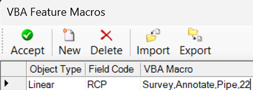
Next time the user imports survey data with Field code RCP it will create a 3D pipe in the dgn.
Points
There are two settings in the Point option. They are Import Coordinate Records and Control Point Features.
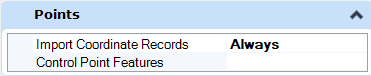
The settings for Import Control Records are as follows.
- Always - Any coordinates found in RAW, or ASCII data files are imported as Point Features.
- Never - Any coordinates found in RAW, or ASCII data files are not imported as Point Features.
- As Control - Any coordinates found in RAW, or ASCII data files are imported as Control Points.
- As Control By Feature Definition - Any coordinates found in RAW or ASCII data files that match the Control Point Features defined in the Control Point Features option are imported as Control Points.
The Control Point Features option allows the user to define which (if any) Point Features are imported as Control Points when the Import Coordinates Records option is set to As Control By Feature Definition.
Linking Codes
The Linking Codes settings specify how survey field codes in RAW and ASCII data are interpreted and used by Survey to create Linear Features. The Link Codes option allows the user to specify which codes will be used by the survey crew in the field to Begin & End Linear Features, specify Curve points, and perform special functions such as Closing a Linear Feature. The Link Code Position has two settings, After Point Feature Definition and Before Point Feature Definition depending on how the survey crew codes the data in the field.
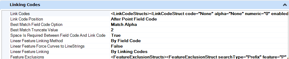
The Linear Feature Linking Method has the following settings:
- By Field Code - Linear Features begin with the Point having a Start Link Code and include all similar Point Features in order until an End Link Code is encountered.
- By Consecutive Field Code - Linear Features being with the Point having a Start Link Code and include all similar Point Features in Point Name order until an End Link Code is encountered.
- Connect All Matching Field Codes - All points with similar Point Features are stored into a single Linear Feature.
Linear Feature Linking has two settings By Linking Codes and Force Point List Features. Linking Codes uses the Link Codes present in RAW or ASCII files to create only Dynamic Link Linear Features upon import. Force Point List Features creates only Point List Linear Features upon the initial import. Feature Exclusions allow the user to specify which (if any) Features are to be excluded from creating Linear Features.
| Options | Description |
|---|---|
| Start | It will begin creating a Linear Feature. |
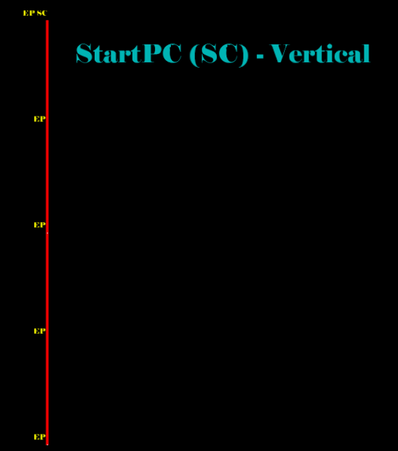
| StartPC | It will start a linear feature in Arc Mode. |
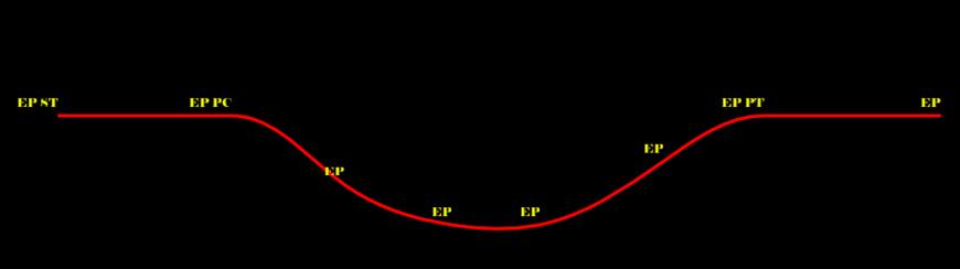
| ArcPC | It specifies the beginning of a tangential arc or curve within a Linear Feature. |
| NonTanPC | It specifies the beginning of a non-tangential arc or curve within a Linear Feature. |
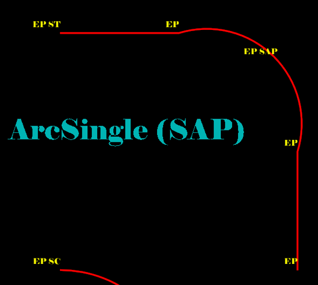
| ArcSingle | It creates a three-point arc with previous and next points (does not work at the beginning or end of a Linear Feature). |
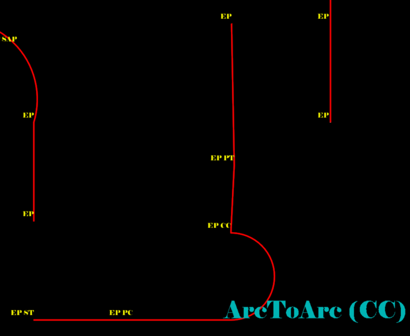
| ArcToArc | It will end the previous tangent arc and begins another tangent arc (must be preceded by ArcPC). |
| NonTanPT | It specifies the end of a non-tangential arc or curve within a Linear Feature. |
| ArcPT | It specifies the end of a tangential arc or curve within a Linear Feature. |
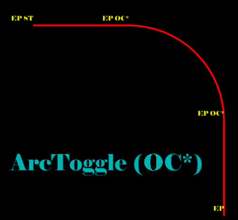
| ArcToggle | It toggles between NonTanPC and NonTanPT (depends on pairing). |
| End | It will end the linear feature (not necessary in most cases). |
| CloseShape | It closes the ends of the linear feature by adding a right angle at both ends and intersecting. |
| Close | It closes the Linear Feature back to the first point. |
Control Codes
Control codes must be assigned after the Field code. Control codes can only be Alpha values. Control and Linking codes can both be used on the same point if the Control code is last. Control codes must be separated from the Field or Linking code with a space.
| Options | Description |
|---|---|
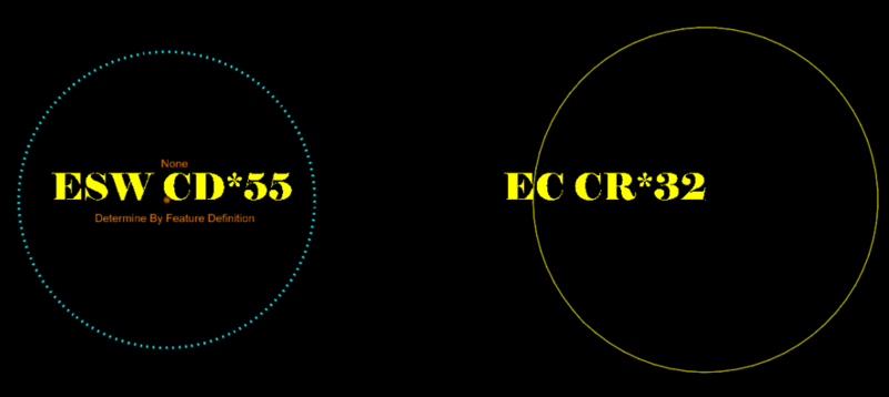
| CircleDiameter | It draws a circle of specified diameter around this point (must be within Linear Feature). |
| CircleRadius | It draws a circle with a specified radius around this point (must be within Linear Feature). |
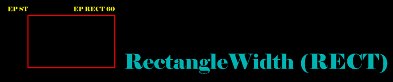
| RectangleWidth | It draws a rectangle from two points and specified width (must be within Linear Feature). |
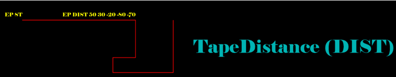
| TapeDistance | It applies field-measured distances to the Linear Feature. All measurements are applied 90 degrees from the previous segment. Positive values turn right, and negative values turn left. (must be within Linear Feature). |
| JoinPoint | It will join this point to a specified point name (does NOT have to be in linear feature). |
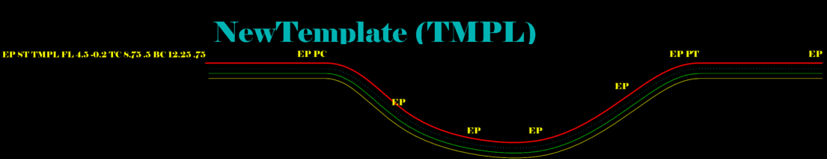
| NewTemplate | It is as same as InRoads TMPL Consecutive Start codes will get this linear feature paralleled and translated based on initial points. |
| Elevation | It will set the Elevation of this point. |
| UpDown | It changes the final elevation coordinate of the point by the value entered. |
| LeftRight | It changes the final coordinate of the point by adjusting the left (-) or right (+) of measured observation by the value entered. |
| FrontBack | It Changes the final coordinate of the point by adding or subtracting a distance from the measured distance. |
| AttributeName | It is one method of getting attributes for a point (pairs with Value). |
| AttributeValue | It is one method of getting attributes for a point (pairs with Name). |
| AttributeArray | It is one method of getting attributes for a point (Names and Values in an array). |
| TerrainSpot | It will be included in DTM as a spot. |
| TerrainNoSpot | It will be not included in DTM. |
| TerrainBreak | It will be included in DTM as a break. |
| TerrainNoBreak | It will be not included in DTM |
The link above contains an example DGN/XIN/CSV file and zip files that demonstrate each of the linking codes available in the OpenRoads Survey. Contents include:
Points Coding
- Point-Coding-STATIC.dgn - DGN file exported from the Survey field book. (i.e., graphics are no longer ruled to the survey field book) This DGN file shows an example of each of the linking codes but is not linked to an active field book, so no changes can be made to the survey data.
- Point-Coding-LIVE.dgn - DGN file containing a field book imported from the CSV file.
- point-coding.csv - ASCII point file to demonstrate linking codes
- point-coding.tiw - TIW file used to import CSV file


 Survey Control Codes


Survey Control codes with numeric values (RECT/DIST/JPT/CR/CD) do not work if "Space Required Between Field Codes" is False
Even though link codes and control codes are in the same list they behave differently when parsing. There is a rule that all Control codes must be space separated and before the items that define the control. Control Codes are not linking codes.
Not Valid
Valid
How do LR, UD, and FB Control Codes Work
These are not Linking codes, these are control codes. They only work for RAW data (Do not work for ASCII), the field data must have Horizontal angles, vertical angles, and slope distance. They will NOT work for ASCII data.
These can be user-defined, they don't have to be LR, UD, or FB they could be for example AB or LR*, etc
Usually, they are placed after the Feature code then a space then the value.
In the following example on the first line TREE is the feature code, then there is a space then the code LR then the value -10 which means to the left of the point with the observer looking to the set-up instrument (so the new coordinates of the point will fall to his left).
- SS,OPA5,FPB61,AR339.4550,ZE89.5813,SD32.64,--TREE LR -10
- SS,OPA5,FPB62,AR297.5959,ZE90.0353,SD29.82,--TREE UD 100
- SS,OPA5,FPB63,AR278.2719,ZE90.0000,SD57.14,--TREE FB 40
UD 100 means elevation UP 100 feet from the original calculated elevation, if the original elevation was 1000 then the new elevation is 1100
FB 40 means 40 to the back of the point (observer looking at the set-up instrument) therefore if the original calculated distance is 100, the new distance is 140
These will also work:
- SS,OPA5,FPB61,AR339.4550,ZE89.5813,SD32.64,--TREE LR*-10
- SS,OPA5,FPB62,AR297.5959,ZE90.0353,SD29.82,--TREE UD*100
- SS,OPA5,FPB63,AR278.2719,ZE90.0000,SD57.14,--TREE FB*40
The UpDown, LeftRight, and FrontBack control codes only change the position of observation records (RAW data). They will not affect coordinate records (ASCII)
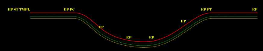
Using linear feature templates (TMPL code) in Survey
The user can use the linear feature templates (TMPL) while collecting survey data:
Survey linear feature templates and the TMPL control code have been enhanced to allow multiple linear features to be collected at once.
Start a new feature like normal then append TMPL Feature_Code Horizontal_Offset Vertical_Offset, etc.
Example: Start a line on the GUT and automatically collect Top of Curb (TC), Back of Curb (BC), and EP.
GUT ST TMPL TC 0.1 0.5 BC 0.5 .05 EP -2.0 0.1 GUT GUT GUT PC GUT GUT PT GUT GUT END
Or locate the other linear features with a field shot to define the Horizontal and Vertical offset.
GUT ST TMPL TC ST BC ST EP ST GUT GUT GUT PC GUT GUT PT GUT GUT END
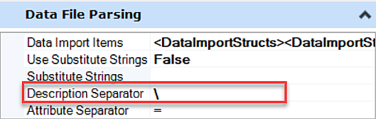
Data File Parsing
Data Import Items allow the user to specify the various survey data formats that will be shown when importing data into Field Books.
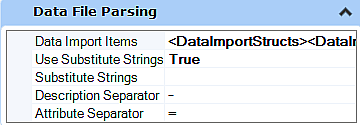
Use Substitute Strings is a True/False setting that allows the user to define replacement values in the Substitute Strings options for field entered Features when set to True.
Adjustment Defaults
Allows the user to set approximations for the errors inherent in their surveying equipment and measurement procedures.

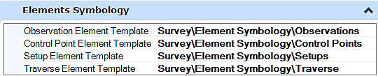
Element Symbology
This option allows the user to set a Template Style to control symbology for Observations, Control Points, and Setups when importing RAW surveying data files. Also, this option allows the user to set the appropriate size for Observations, Control Points, and Setups when importing RAW surveying data files.
Terrain Model
Create Terrain Model for All Field Books is a True/False setting that automatically creates a Terrain Model from all Field Books as they are imported when set to True.

Name allows the user to specify the Name given to the Terrain Model automatically created when the Create Terrain Model for All Field Books option is set to True.
Feature Definition allows the user to specify the Feature Definition used by the Terrain Model automatically created when the Create Terrain Model for All Field Books option is set to True.
Edge Method allows the user to specify the Edge Method used in the creation of the Terrain Model automatically created when the Create Terrain Model for All Field Books option is set to True. Options are None, Remove Slivers, and Max Triangle Length.
Length allows the user to specify the Max Triangle Length to be used when the Edge Method is set to Max Triangle Length and the Create Terrain Model for All Field Books option is set to True.